

|
Applied Geophysics : Seismics
|
Seismometer Documentation
- Table of Contents -
- Principles of Operation -
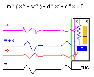
A seismometer is a device that enables us to observe and / or record a
ground motion,
and it in general consists of
-
- an inertial system,
- i.e. a movable mass, coupled to a rigid case by a spring and a damping
device,
- and
-
- a transducer system,
- that produces an output signal, corresponding to the relative motion of
the case with respect to the mass, serving as a "fixed"
reference point, because of its great inertia.
Mechanical System :
A qualitative estimate of the behavior of the mechanical system can be
derived assuming a harmonic ground ( = case ) motion :
- for "very high" frequencies of the ground motion
( compared to the so called natural frequency of the system ),
the suspended mass tends to keep its absolute position, and its displacement
relative to the case represents the ground displacement,
- for "very low" frequencies of the ground motion, the mass
tends to follow the case motion and the relative displace ment tends
towards zero.
A quantitative description of this obvious high pass characteristic,
relating the relative mass displacement to the ground displacement,
especially between the extrema "very low" and
"very high"
frequency, can be derived from the equilibrum of all external and
internal forces acting on the mass, and leads to a
second order linear differential equation

relating the quantities describing the ground motion
|
x(t), x'(t) and x"(t)
|
= |
relative mass displacement, velocity and acceleration
|
|
and
|
|
|
|
w"(t)
|
= |
ground ( = case ) acceleration
|
to the characteristic parameters of the mechanical system :
|
m [kg]
|
= |
suspended mass,
resulting in a inertial force, proportional to the total acceleration
x"(t) + w"(t)
|
|
d [Ns/m]
|
= |
damping constant,
producing a force, proportional to the velocity x'(t) and reflecting
internal losses
|
|
and
|
|
c [N/m]
|
= |
spring constant,
resulting in a force, proportional to the excursion of the mass from its
equilibrum ( = zero ) position,
i.e. proportional to the relative mass displacement x(t).
|
- The negative sign of the forces, contributing to the differential equation,
denotes the fact, that the forces are directed opposite to the respective
component of motion.
- The inertial force refers to the sum
x"(t) + w"(t),
- i.e. the total ( absolute ) acceleration of the
mass,
- whereas damping and spring forces are
- internal to the system, acting between the seismometer case
and the mass.
- ! The mechanical system described here refers to a seismometer with
a mass, restricted to a linear movement ( 1 degree of
freedom ),
- especially to a vertical seismometer in
Sensitivity determination ( see "weight lift
test" ).
- All other formulations are valid for horizontal instruments as
well !
- ! For seismometers with a mass mounted to a rigid beam
rotating about a hinge ( => 1 degree of freedom ),
- the state of the system is described by
- the rotation of the beam
- ( angular excursion, velocity and acceleration ),
- and derived from
- the equilibrum of all internal and external moments, i.e.
- angular acceleration × moment of inertia,
- ground acceleration × mass × distance of
center of gravity to hinge line, etc. !
Equation of Motion :
After division by m, the differential equation can be written as

with usual abbreviations

introducing the natural frequency of the system, and a
dimensionless damping constant :

A solution of the differential equation, obtained applying the
Laplace transform, includes
-
- transfer functions, relating
- the relative mass motion ( displacement x(t) or velocity
x'(t) )
- to
- the ground motion ( displacement w(t), velocity w'(t)
or acceleration w"(t) ) or to
- an acceleration p(t) / m, due to a force p(t),
applied to the mass,
- and
-
- the free motion of the mass, depending on
the initial conditions of
- the mechanical system
- ( initial mass displacement x(+0) and mass velocity
x'(+0), relative to the case )
- and of
- the ground motion
- ( initial ground displacement w(+0) and ground velocity
w'(+0) ).
Transducers :
- Displacement transducers,
- mostly capacitance or inductance bridges,
- ( at the beginning of seismometry enlarging mechanical lever systems,
driving a pen, or light beams, deflected by a movable mirror and recorded on
photographic paper ),
- produce an output voltage proportional to the mass displacement
x(t) relative to the case :

- In general these systems have a negligible feedback force acting on the
mechanical system.
! Exception : mechanical lever systems, where the frictional
force of the pen, multiplied by the amplification of the lever system,
acts on the mass !
- Velocity transducers,
- in most cases a cylindrical coil mounted to the mass, and moving in the
annular gap of a permanent magnet fixed to the case
( or vice versa ), and thus producing
- an induced voltage proportional to the rate of the magnetic flux
change within the coil, hence to the velocity x'(t) of the coil
motion relative to the magnet :

- If an external resistance is connected to the coil, the current
flow in the coil, i.e. in the field of the permanent magnet, results in
a force,
- proportional the current by the same motor constant G [N/A]
( = [Vs/m] ),
- and
- acting on the mechanical system.
- In general, capacitive and inductive contributions to the total ciircuit
resistance can be neglected within the relevant frequency range, i.e.
voltage and current, hence
- force and velocity x'(t), are in phase :
- The electromechanical feedback results in a contribution to the
damping of the mechanical system, and is adjustable via the
external resistance.
Table of Contents
Principle of Operation
Mechanical System
Equation of Motion
Transducers
- Applets -
- The applet
Seismometer Demo demonstrates
- the displacement and velocity output
- ( together with the absolute mass displacement
x(t) + w(t) )
- for various types of ground displacement w(t) and for a wide range
of parameters
- ( i.e. natural frequency, damping of the seismometer, and
frequency / time scale of the ground motioni ).
- In a separate frame, the normalized amplitude and phase response of
displacement and velocity output with respect to displacement, velocity
and acceleration of the ground motion can be displayed.
- In the Applet
Seismometer Calibration,
- the natural frequency is determined by observing the phase shift between
a harmonic current in a calibration coil and the resulting output voltage
of a signal coil.
- The seismometer damping, resulting from various settings of the
external resistance in a coil circuit, is determined from the free
motion of the seismometer mass, initiated either by switching on and off
a dc current in the calibration coil or by dropping and lifting a small
additional mass ( "weight lift test" ).
- The peak and trough amplitudes of the damping tests may be picked
automatically and saved to calculate the open circuit damping and the so
called "critical damping resistance" by a least squares fit.
- In addition the motor constants of calibration and signal coil are
calculated, and the results of the calibration procedure are displayed
together with their "true" values, not known in advance.
- More applets to seismometry ( LP-seismometer with
LaCoste suspension, Comparison of transfer functions of some historical and
actual seismographs, and others ) can be found
- at
Geophysics Dept., TU Clausthal
- and
- at the author's
Homepage.
Table of Contents
Applets
- Basics and some Applications of the Laplace Transform -
The Laplace transform G(s) of a function g(t) and the inverse
Lapace transform :

Some rules :
-
Differentiation in the time domain corresponds to a
multiplication by s in in the frequency domain, taking into
account initial values of the time function :

- g(+0) and g'(+0) representing the initial values
- lim g(t) and lim g'(t) for
t → +0,
- i.e. for t approaching zero from the positive side t > 0 of the time axis.
-
Multiplication in the frequency domain corresponds to convolution
in the time domain :

-
Limits :

provided that the limits of g(t) exist, these relations are very useful for
the determination of these limits directly from G(s).
Applications to the equation of motion of a
seismometer :
- Substituting
- X(s) = transform of the mass displacement x(t)
- and
- W(s) = transform of the ground displacement w(t)
- to the differential equation in the time domain

- yields an algebraic equation in the frequency domain

- with
- h(t), H(s) = the impulse response of the system
and its transform
( = transfer function ),
- z(t), Z(s) =
the free displacement of the mass
and its transform,
- due to the initial conditions x(+0), x'(+0) of the
seismometer and w(+0), w'(+0) of the ground motion.
- and

- ( H(s) = high pass ),
- where h(t), z(t) can be taken from
tables of the Laplace transform.
- If the ground is at rest for t &le 0
( w(+0), w'(+0) = 0 ) then :

- with z(+0) = x(+0) ( from limits rulei ).
- Applying the differentiation rule to X(s) leads to a mass
velocity of

- with z'(+0) = x'(+0) for
w(+0), w'(+0) = 0
( from limit rule ).
- ! The same functions h(t),H(s) relating the mass displacement to
the ground displacement as well relate the mass velocity to the ground
velocity&nbs;!
- Substituting a(t) for the ground acceleration w"(t)
( transform = A(s) ) leads to

- ( L(s) = low pass ),
- relating the mass displacement to the normalized acceleration

- and
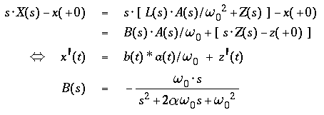
- ( B(s) = band pass ),
- relating the mass velocity to the normalized acceleration

Table of Contents
Laplace Transform
Some Rules
Applications
- Transfer Functions -
For the functions of time involved (i.e. seimic signals of finite amplitude
and duration, or impulse responses of causal systems like seismometers),
the domain of definition of the Laplace transform
includes the imaginary axis in the complex s-plane.
The transfer functions
H(s), L(s) and B(s)
of a seismometer usually are visualized and discussed considering the
amplitudes |H|, |L|, |B| and phases arg{H}, arg{L} and arg{B}
on the imaginary axis with a frequency scale, normalized by the
natural frequency of the seismometer.
The Transfer Function H(s)
relates the mass displacement x(t) to the ground displacement
w(t) and the mass velocity x'(t) to the ground velocity
w'(t).
It corresponds to a normalized second order high pass
characteristic :
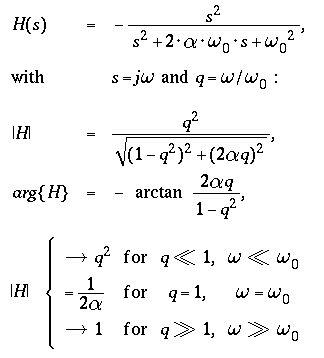
For signals in the frequency range above the natural frequency,
seismometers
-
equipped with a displacement transducer are displacement meters,
-
equipped with a velocity transducer are velocity meters.
The Transfer Function L(s)
relates the mass displacement x(t) to the ground acceleration
w"(t), and corresponds to a normalized second order
low pass characteristic :
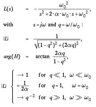
For signals in the frequency range below the natural frequency,
-
seismometers equipped with a displacement transducer are
accelerometers
( gravity meters, if sensitive to vertical accelerations ).
The Transfer Function B(s)
relates the mass velocity x'(t) to the ground acceleration
w"(t)
( or an equivalent acceleration p(t) / m, due to an external
force p(t) ) or
the mass displacemen x(t) to the ground velocity w'(t),
and corresponds to a normalized second order band pass
characteristic :
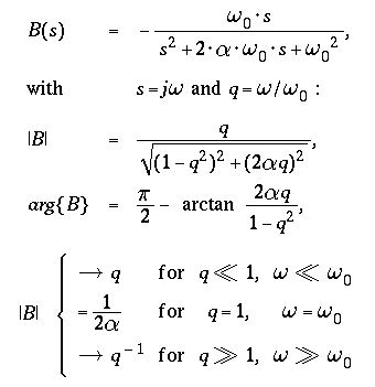
For large damping values the amplitude |B| is "flat" within a frequency
band around the natural frequency of the seismometer, roughly :

For signals within this frequency range, seismometers
-
equipped with a velocity transducer are acceleration meters,
-
equipped with a displacement transducer are velocity meters,
Table of Contents
Transfer Functions
High Pass H(s)
Low Pass L(s)
Band Pass B(s)
- Free Motion of the Seismometer Mass -
A procedure, frequently performed to test or calibrate a seismometer, is to
release the mass at t = 0 from a fixed position, and to observe / record
the free motion of the mass.
For the corresponding initial conditions

the Laplace transforms for displacement and
velocity are :
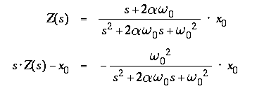
leading to a mass displacement z(t) and velocity z'(t) in the
time domain of
( from a table of Laplace transforms ) :
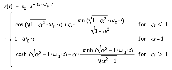
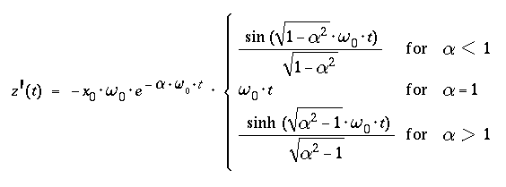
- For times t ≤ 0
- z(t) = x(+0) and z'(t) = 0,
- and for times t > 0
- the mass performes damped oscilations about x = 0
( α < 1 )
- or
- returns to x = 0 witout overshoot
- ( aperiodic limit α = 1,
"creeping" &alpha > 1 ).
Table of Contents
Free Motion
- Parameter Determination -
- The normalized transfer functions of a seismometer are determined by
- the natural frequency
- and
- the damping
- of the mechanical system.
- The two parameters
- "critical damping resistance" ( CDR )
- and
- open circuit damping
- allow the adjustment of a desired damping value,
avoiding a tedious trial-and-error procedure.
- Finally, to reconstruct the "true" ground motion from the
output signal,
- the sensitivity K [V/m] or G [Vs/m]
- of the respective transducer is needed.
The Natural Frequency
of a seismometer can be determined by from the transfer function
B(s) :
Assuming a force p(t) caused by an harmonic current i(t) in a
calibration coil, and concernig the output voltage u(t) of a signal coil :
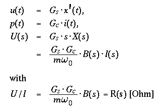
R(s) = U(s) / I(s) can be interpreted as a complex,
frequency dependent impedance, introducing a phase shift of
amount arg{B} between the harmonic current i(t) from an external
current source and the resulting harmonic output voltage u(t) of a
signal coil :
- The graph of u(t) versus i(t)
( on an oscilloscope or an xy-recorder )
- is an ellipse for arg{B} ≠ 0, reduced to
- a straight line for arg{B} = 0
( B = 1 / 2α for q = 1, see above ).
- This is an extremely sensitive indication of q = 1,
- ( i.e. driving frequency equal to the natural frequency ),
- and in general it reduces the error of determination of the natural
frequency of a seismometer to
- the adjustment / measurement error of the output frequency of the
current source.
- ( see DISPLAY U_SIG / I_CAL of the Applet
Seismometer Calibration. )
( For single coil systems, the above procedure is applicable with minor
modifications to the electric measuring circuit, and with a slightly reduced
sensitivity due to the contribution of the coil resistance to the real part
of the total "seismometer impedance" R(s). )
The Damping
of a seismometer usually is calculated from the
free motion of the mass, a
damped oscillation about zero for α < 1.
The output voltage of a displacement or velocity transducer
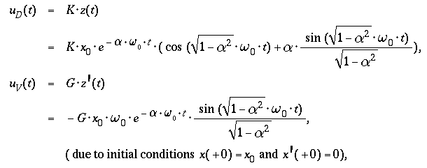
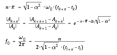
- allows to calculate the damping
- from the decay of amplitude extrema,
- the natural frequency
- from the distance of zero crossings,
- both occurring at phase differences of multiples of π
( = 180 [Deg] ) in the argument of the
sine function :
( see DISPLAY U_SIG / TIME of the Applet
Seismometer Calibration )
Unfortunately this evaluation of the free motion is restricted to damping
values α < approx. 0.7, where a measurable overshoot of the
signal trace occurs.
The natural frequency should preferrably be determined observing the
phase shift arg{B(s)},
a method more accurate
( and less dependent on the seismometer damping ).
A similiar method, concerning the amplitude |B(s)| of the
tranfer function B(s), can be applied to calculate damping
values α distinctly > 1 from the corner frequencies of
the band pass characteristic.
"Critical Damping Resistance"
The force p(t) between coil and magnet
( between case and mass ) is proportional to the current
i(t) in the coil with the motor constant G [N/A]
( = generator constant G [Vs/m] ).
In general, capacitive and inductive contributions to the total cicuit
resistance are negligible for the relevant frequency range :
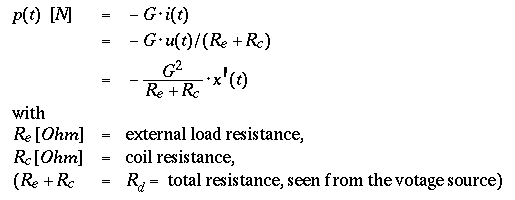
The force p(t) is proportional to the velocity x'(t),
directed opposit to the motion ( negative sign ), and thus
contibutes to the damping of the system
( see mechanical sytem and
equationof motion ) :
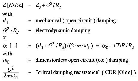
- By variing the external load resistance, the damping of the system can
be adjusted in wide range,
- the lower limit corresponding to the open circuit damping, and
- the upper limit determined by G^2 and coil resistance.
- The values of damping α observed for different values of
the the load resistance,
- displayed versus 1/(total resistance), should lie
on a straight line :
- slope = CDR and
- ordinate intercept = open circuit damping.
- ( The notation "CDR" refers to the fact, that for a total
resistance of the circuit equal to CDR, the electromagnetic damping
contributes with a value of 1 ( = critical ) to the total
damping α. )
Sensitivity
If a seismometer is equipped with a "weight lift" facility,
i.e. if a small additional mass dm ( usually
≤ 1 [g] ) can be dropped onto the movable mass of the
seismometer,
a known external force can be applied ( see
mechanical sytem and
equation of motion ) :
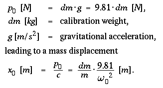
Waiting long enough before lifting the weight, the initial conditions are
x'(+0) = 0 and x(+0) ≠0
(see damping ), leading to :
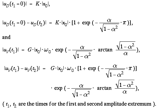
( see DISPLAY DAMP. / 1/R of the Applet
Seismometer Calibration )
A less complicated ( but in general less accurate ) way, to determine
the motor constant G, is to calculate its value from the "critical
damping resistance" :

Finally, the motor constant of a calibration coil may be
determined comparing the amplitudes of a weight lift test to those
of a dc current test for identical damping values.
! In all the above evaluations, unfortunately the seismometer mass m
cannot be eliminated, its value has to be taken from the manufacturer's
specifications !
( Possibly not sufficiently accurate in absolute value, but at least constant
with time, to allow a prameter check from time to time. )
Table of Contents
Parameter Determination
Natural Frequency
Damping
"Critical Damping Resistance"
Sensitivity
Tables of the Laplace Transform
can be found in :
- Abramowitz, M. and I. A. Stegun, Handbook of Mathematical Functions,
Dover Publications, Inc, New york
- Doetsch, G., Anleitung zum praktischen Gebrauch der Laplace Transformation
und der Z-Transformation, R. Oldenbourg Verlag, München.
This page was compiled using
WebEQ.
To make the page printable ( and faster ), the math. formula
applets were converted to GIFs.
More geophysical applets
at
Institut für Geophysik der TU Clausthal
Rev. 15-dec-2006
Comments to
Fritz Keller
( ned gschempfd isch globd gnueg )
Table of Contents
Principle of Operation
Applets
Laplace Transform
Transfer Functions
Free Motion
Tables of Laplace Transform


